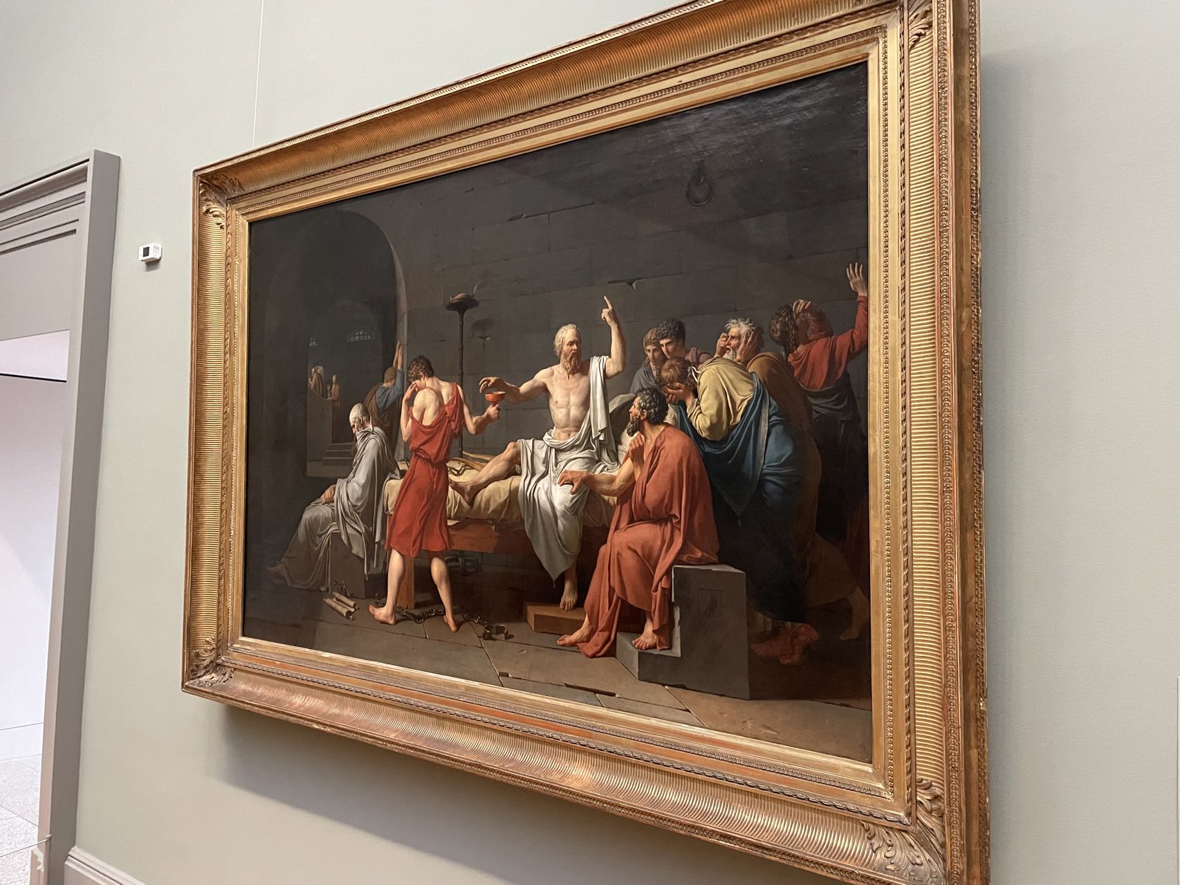


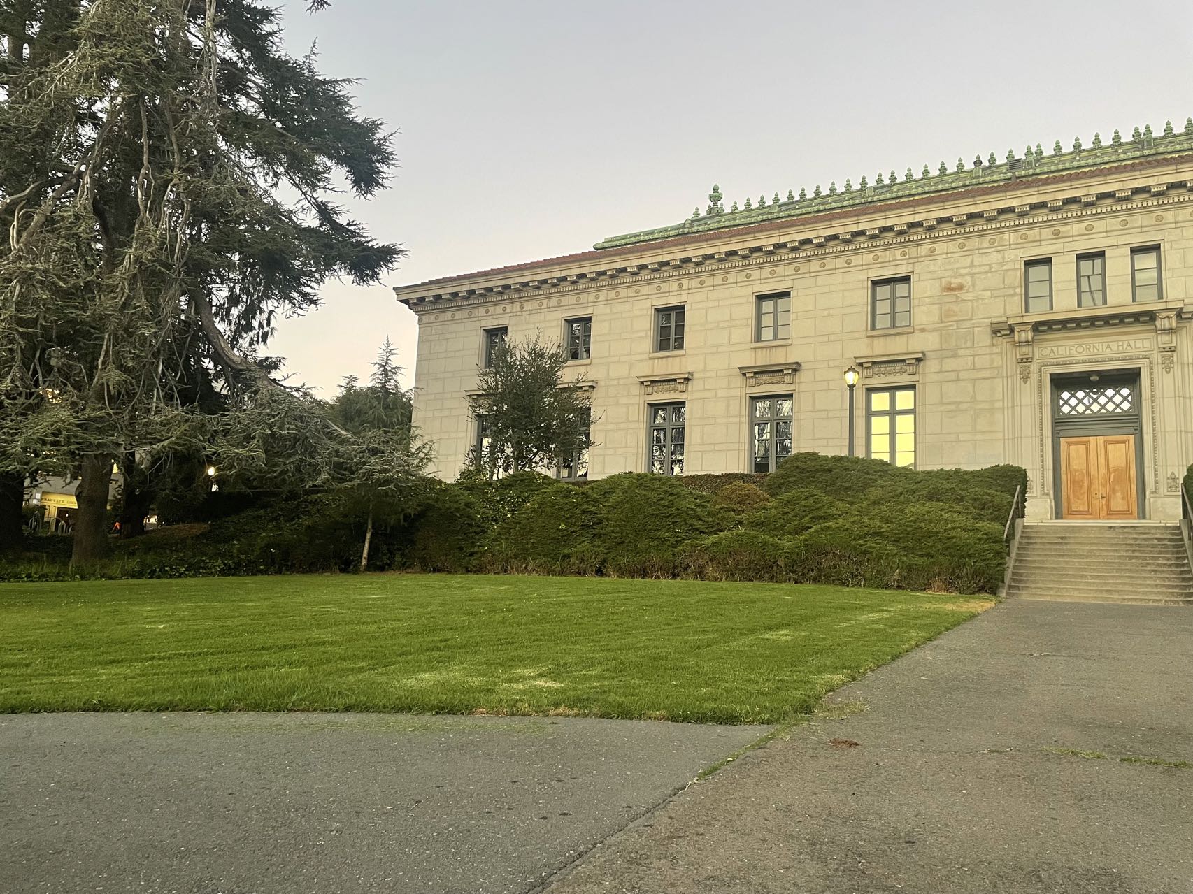
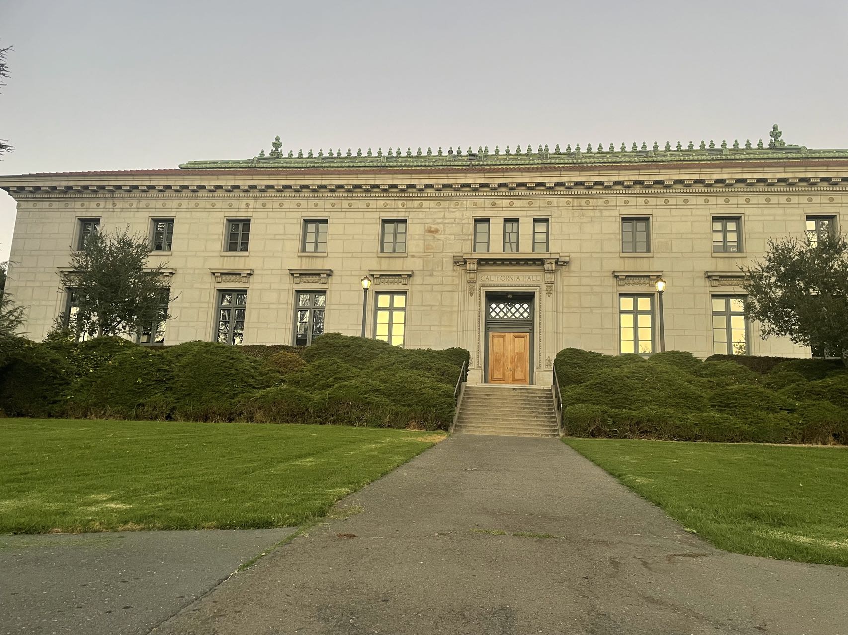
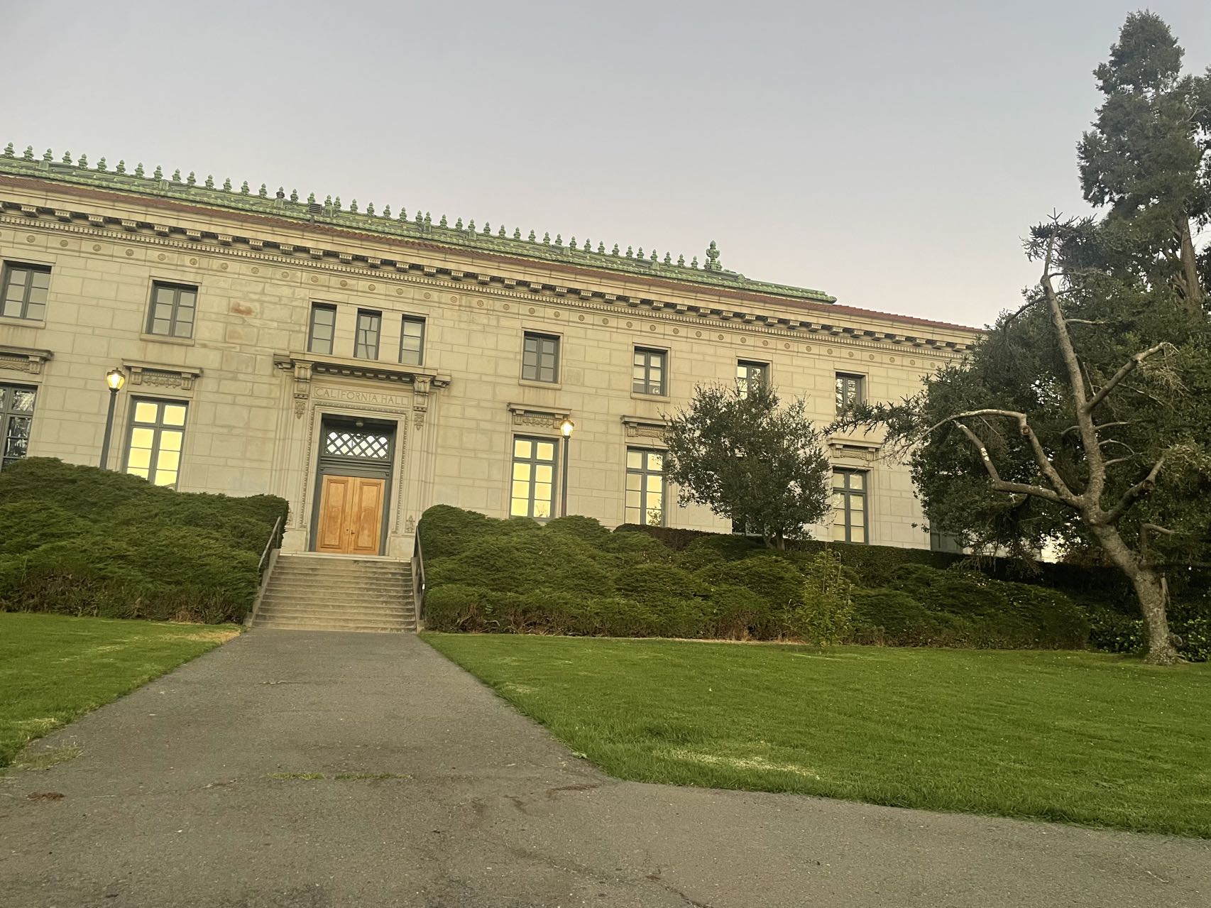
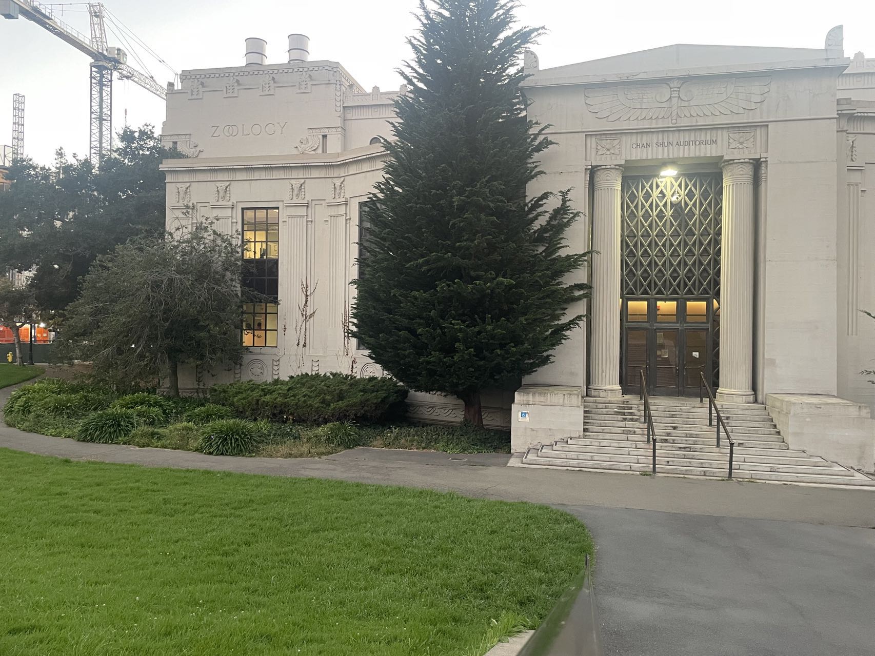
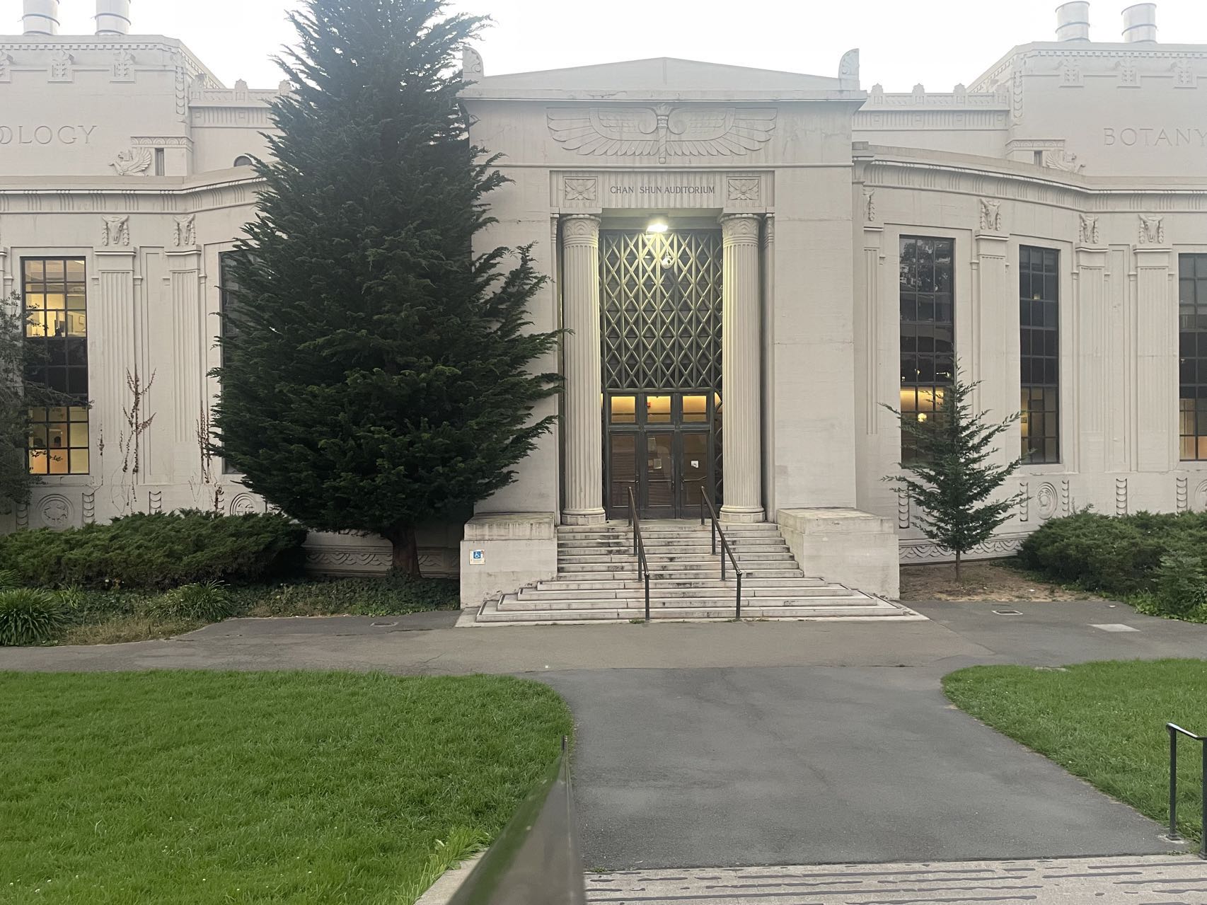
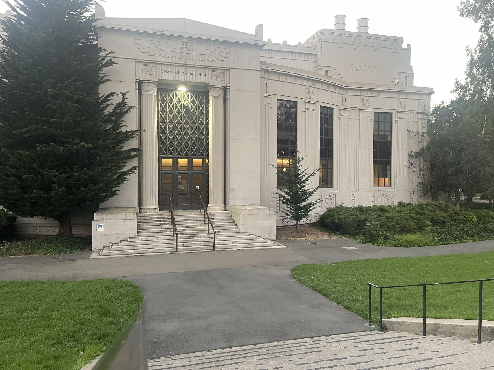
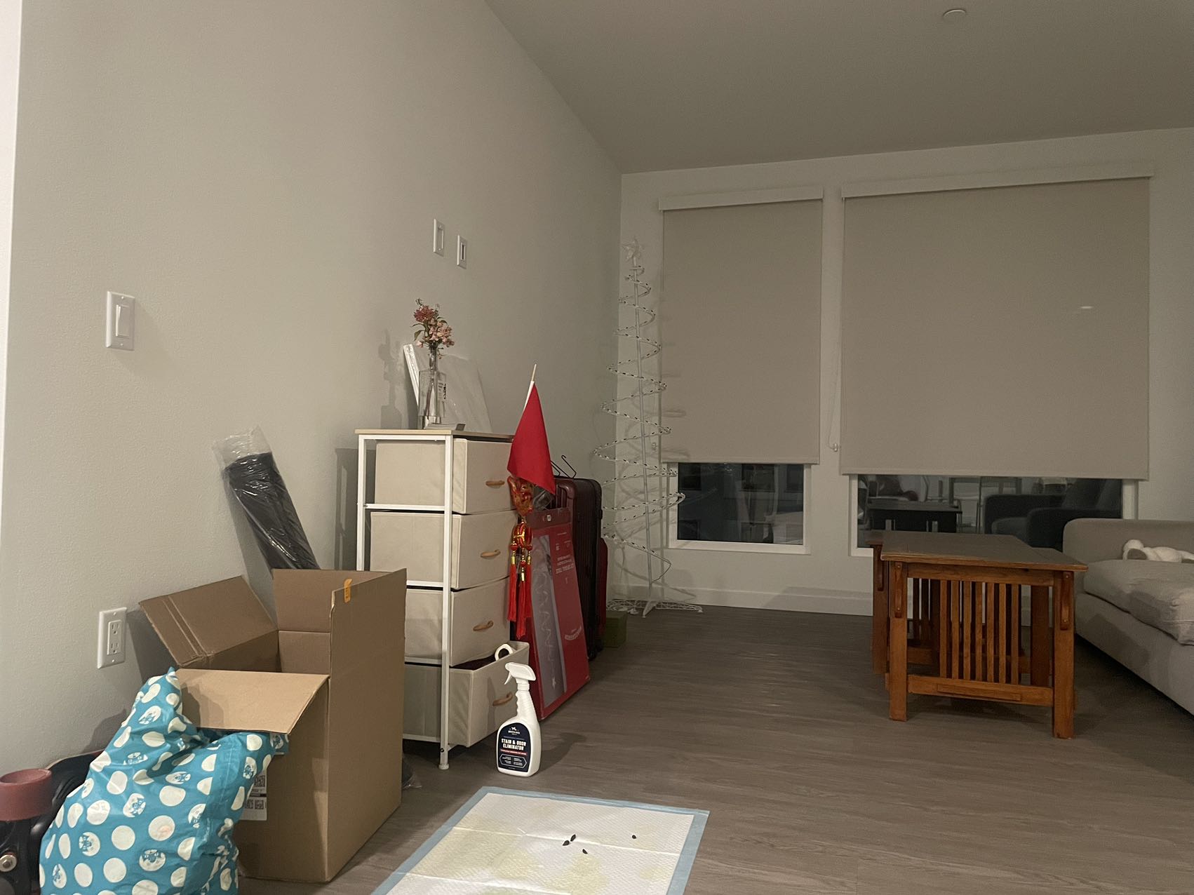
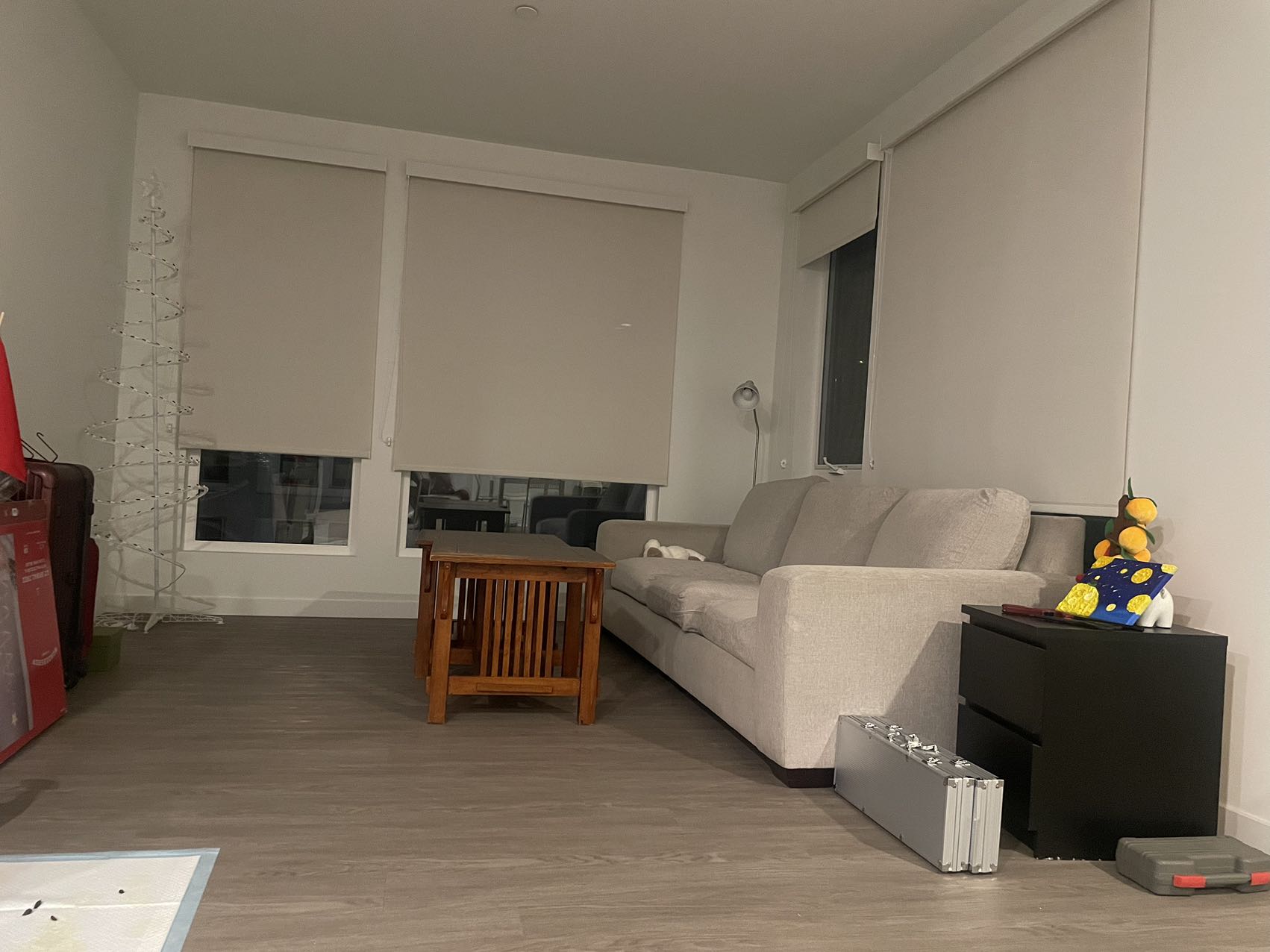
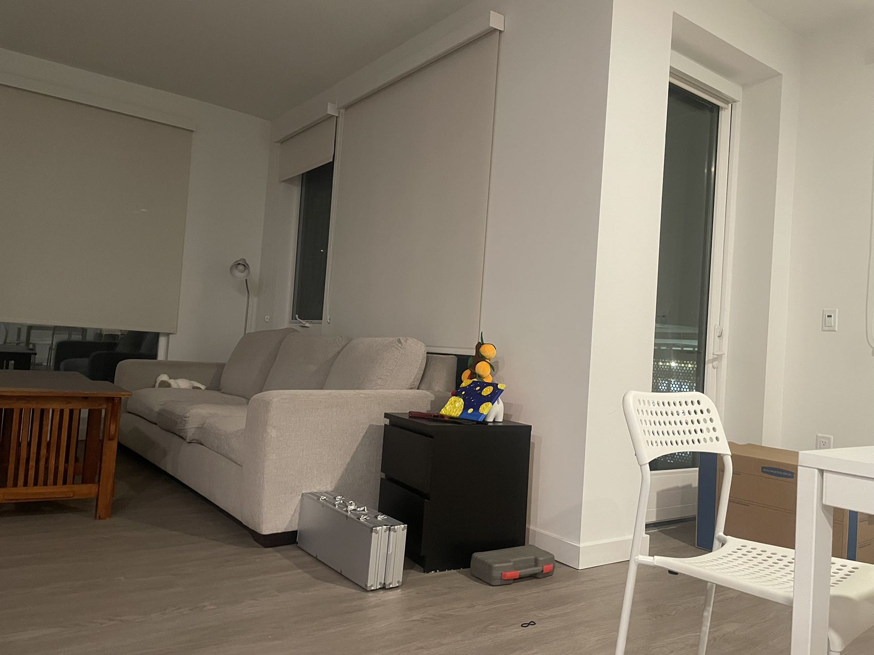
In this project, I first shoot multiple photographs for California Hall, Valley Life Science Building, my living room, etc., align them using homographies, then I inverse warp the images using that homography matrix, and blend them into a mosaic.
Here are all the pictures I used for this project:


I create the function computeH(im1_pts, im2_pts). This basically computes the homography matrix that transforms points from one image to another. Given two sets of corresponding points from two images,
it constructs a system of linear equations and then we solve for the homography matrix using a least-squares.
Here is a more detailed illustaration
For each pair of corresponding points (x1, y1) from the first image and (x2, y2) from the second image, we have:
        x2 = h1x1 + h2y1 + h3 - h7x1x2 - h8y1x2
        y2 = h4x1 + h5y1 + h6 - h7x1y2 - h8y1y2
Then we can write into a matrix form Ah = b, where A is constructed from the points and b is the corresponding points from the second image. A and b are constructed following as:
        A = [
            [x1, y1, 1, 0, 0, 0, -x2x1, -x2y1],
            [0, 0, 0, x1, y1, 1, -y2x1, -y2y1],
            ...
        ]
The b is:
b = [x2, y2, ...]
Then we use least-squares method to solve above system.
Now, we get the solution for h , we append the value 1 to get the 3x3 homography matrix:
        H = [
            [h1, h2, h3],
            [h4, h5, h6],
            [h7, h8, 1]
        ]
I first use a homography matrix H to transform an image. It calculates the new corner positions, creates an output canvas or bounding box, and then uses the inverse homography to map points from the output back to the original image. Then I use function map_coordinates to interpolates pixel values to generate the warped image.
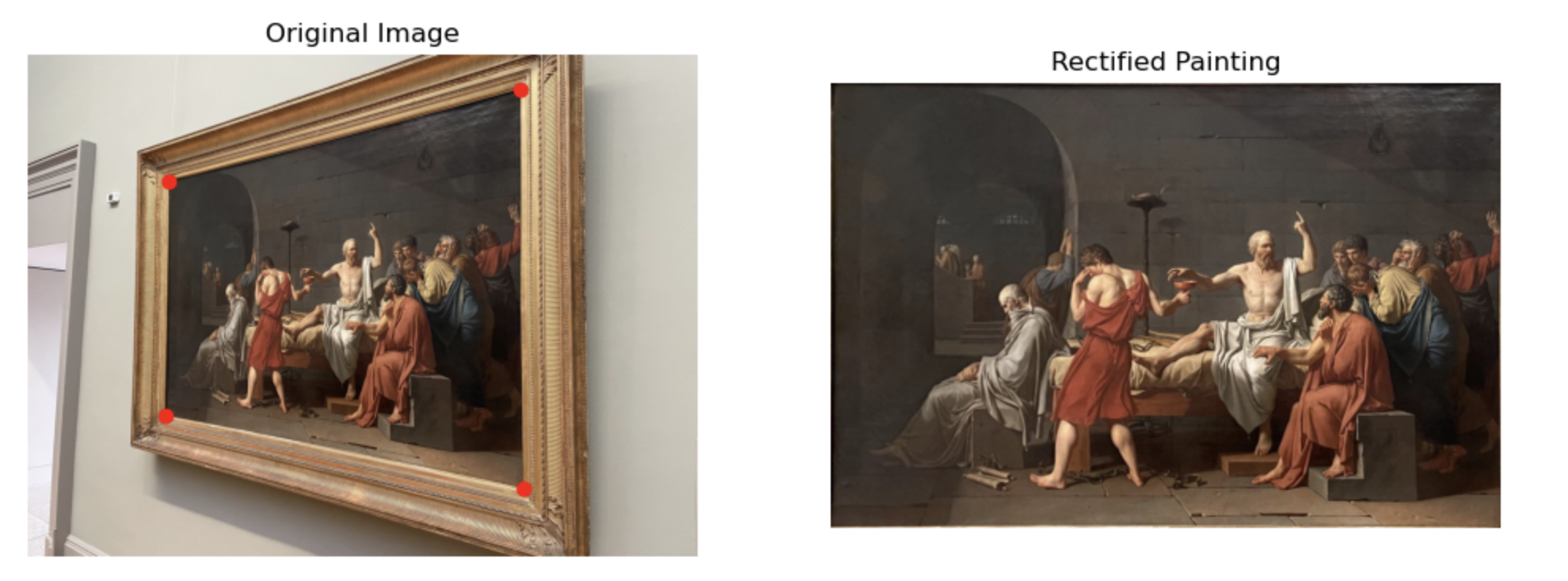
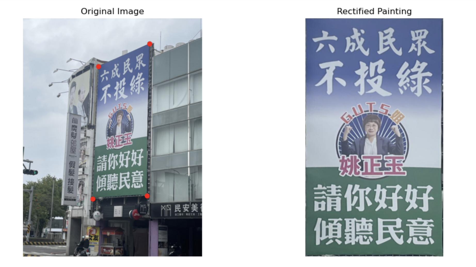
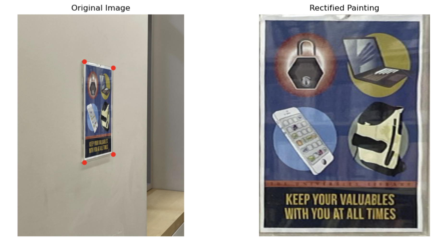
I first mark the four corners of the area I want to rectify, then use the previously computed homography and inverse warping to transform the distorted image into a flat, undistorted image. For clear result, I crop the irrelevant pixels. Here is the results for NYC's paiting, TW's posters , and UCB's random picture:
In this part, I did the following procedure to combine 3 images to a panorama
Here is the results for California Hall, Valley Life Science Building and my living room

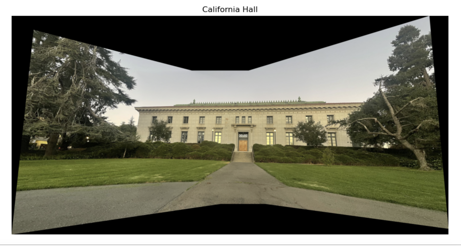

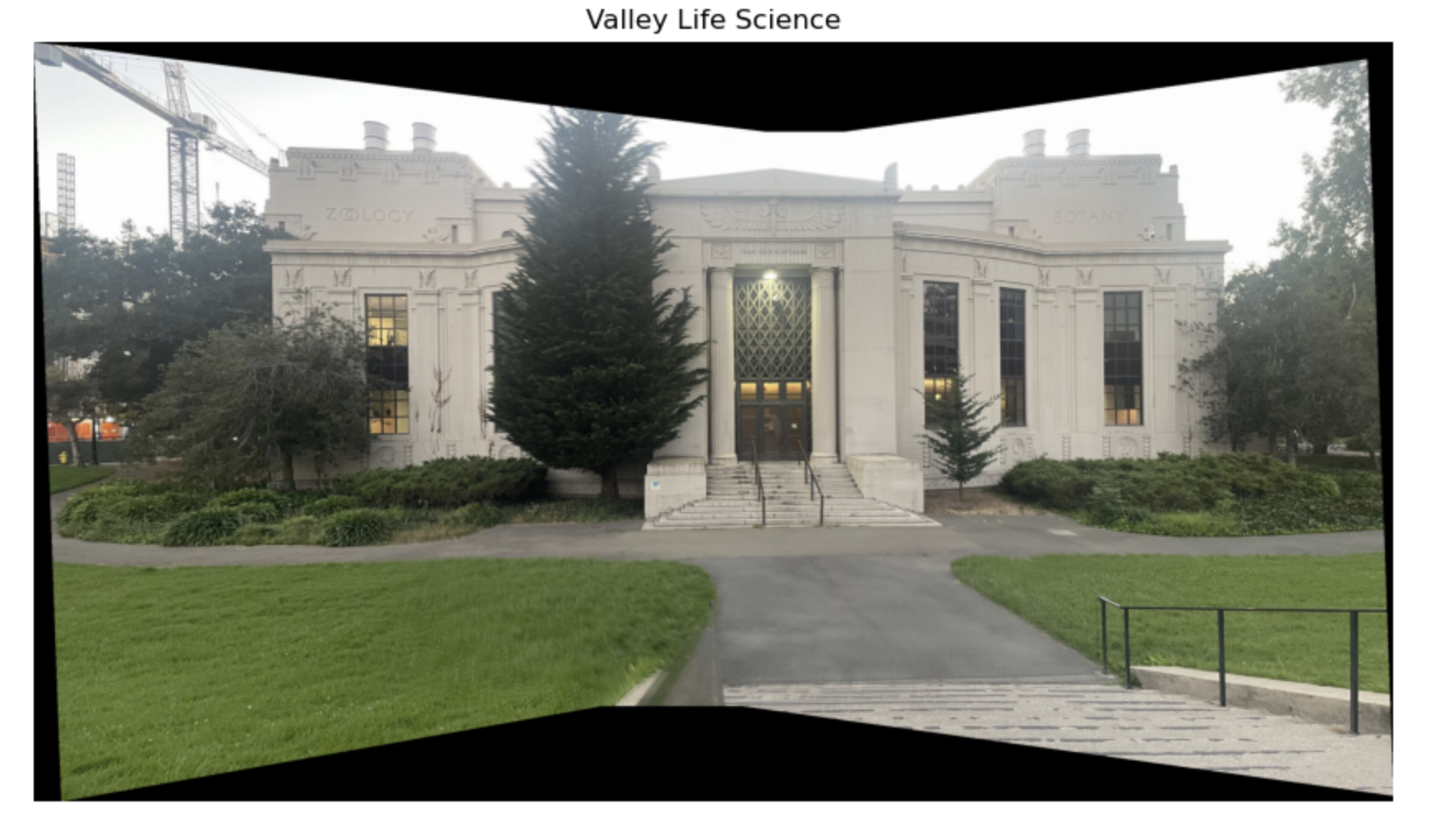

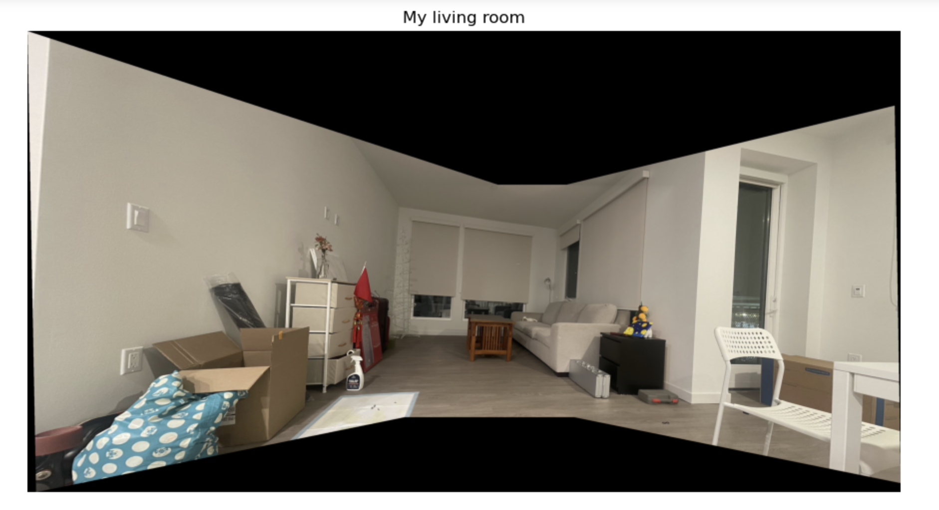
In this project, I follow the paper's instruction to implement harris interest point, ANMS, feature matching, RANSAC to reach auto stiching.
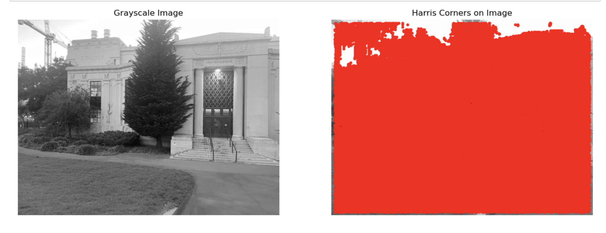
I simply use the sample code to generate Harris Interest Point like this
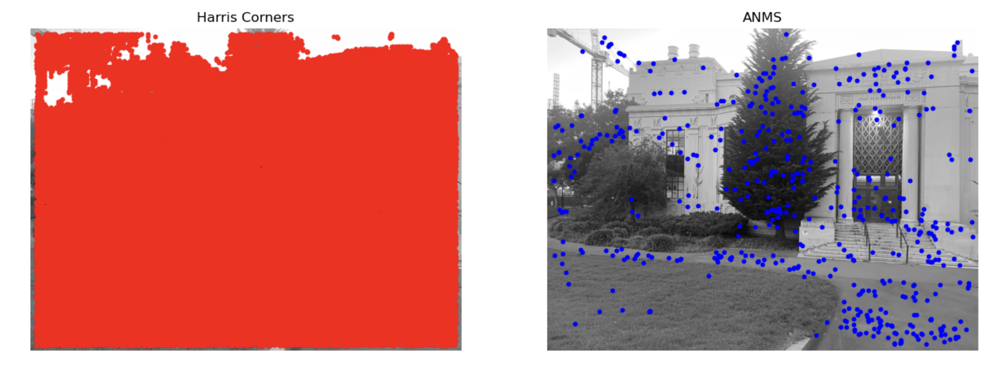
I first build a KD-tree for fast spatial queries on harris interest points. Then I compute suppression radius as following: For each corner point, we iteratively finds neighboring points until it reaches a minimum distance threshold. Among these neighbors, only those with a strength greater than threshold * strength are considered, and the closest distance to these stronger neighbors is considered as the point’s "suppression radius", just as the paper indicates. Finally, we selects the points with the largest suppression radius, ensuring that only the strongest points are got.
For each poin I first check if a square window around it fits within the image. Is so, I make a window centered on the point, and resize it to a smaller patch. Then I do the normalization and store thse descriptors. I randomly choose 4 descriptors to display as following:

I first calculate pairwise differences between features in features1 and features2. Then I get squared Euclidean distances for all feature pairs. Then I sort these distances to get the closest and second-closest matches. After this, I do Lowe’s Ratio Test and return only pairs that pass the ratio test.
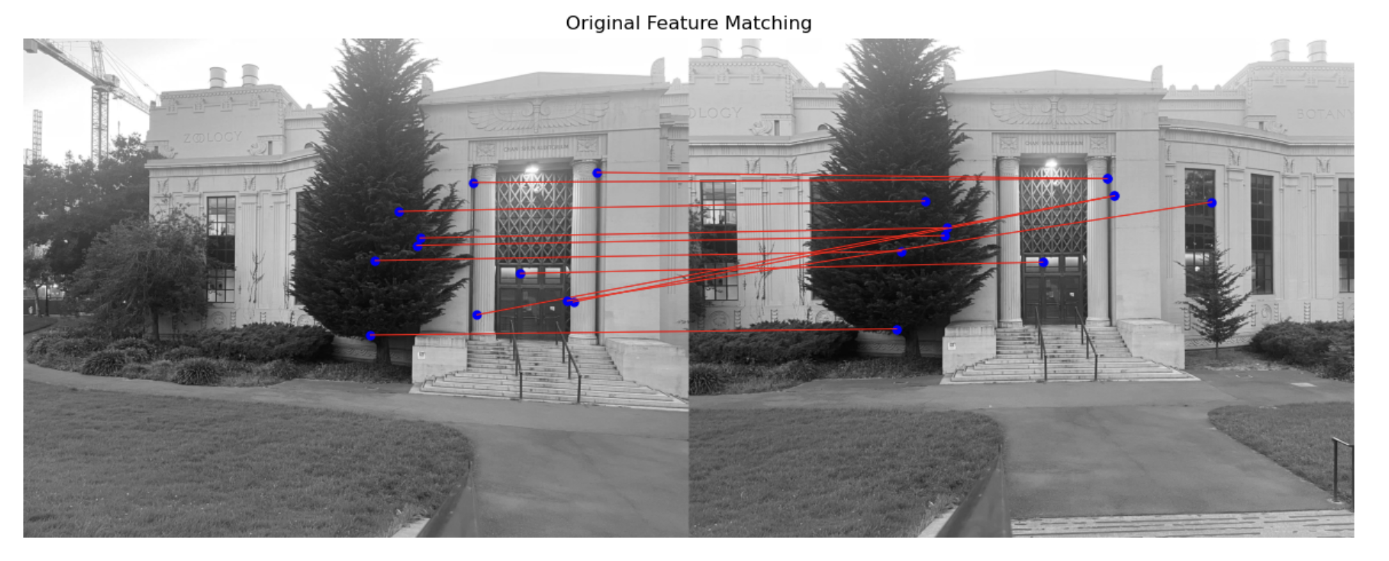
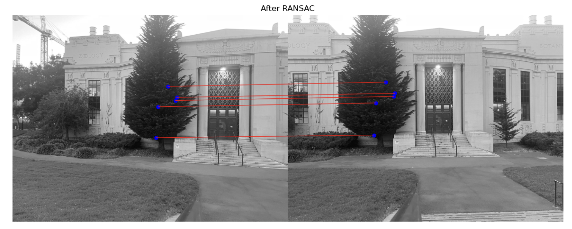
After get feature matching, we still find that there is mismatch in correspondance points. RANSAC helps us address this problem. I iteratively select 4 random point pairs each time. Then I calculate a homography matrix H for the sampled points. Then I transform all points in matched_pts1 using H and counts how many are within a threshold of their counterparts in matched_pts2. Then I return best H and besh inliners.
I used two images from part A and took three additional photos outside my apartment.
The first image is from part A, using manually selected points. The second image shows the corresponding points after RANSAC, and the third image is created using autostitching.


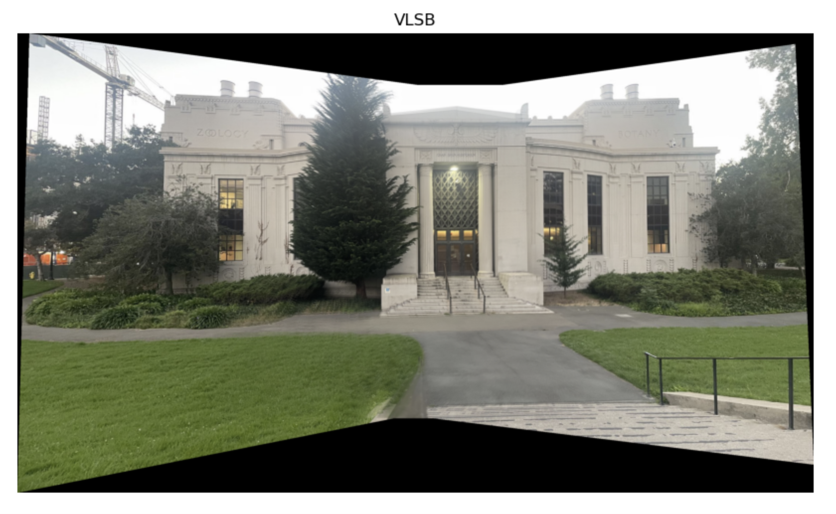
The first image is from part A, using manually selected points. The second image shows the corresponding points after RANSAC, and the third image is created using autostitching.


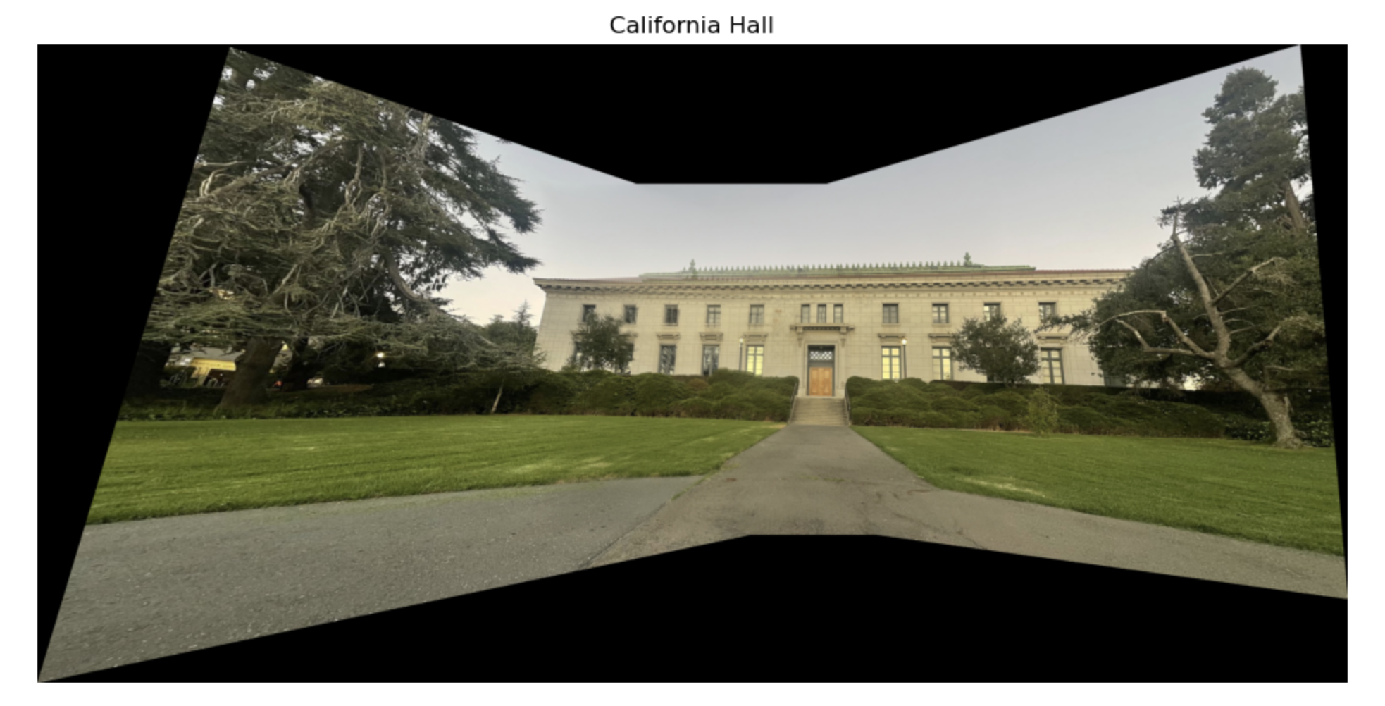
The first image shows the corresponding points after RANSAC, and the second image is created using autostitching.

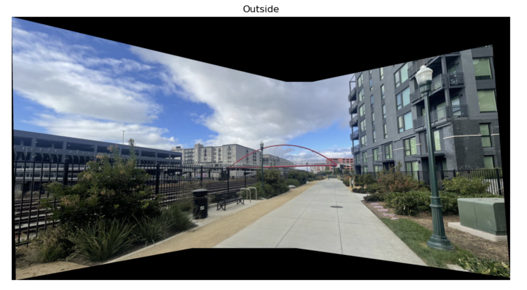
In this projecs, I learn more about image alignment and stitching techniques. I applied homography estimation, image warping, and blending to create seamless panoramas in part A. and I also implement Harris corner detection, ANMS, and Lowe’s Ratio Test for feature matching, To improve alignment accuracy, I implement RANSAC to filter out mismatches. The results are really fascinating and I really enjoy this project it is so cool!